Why Valves Leak and How to Stop It
Sep 27, 2026
Valves are among the most important components in industrial fluid systems. They are used to isolate equipment, start or stop flow, regulate process conditions, prevent backflow, and protect piping systems from abnormal pressure. Whether installed in oil and gas pipelines, chemical plants, municipal water networks, agricultural irrigation systems, power plants, or general industrial facilities, a valve is expected to provide reliable flow control throughout its service life. When a valve is fully closed, however, leakage through the internal sealing area can undermine the entire purpose of isolation.
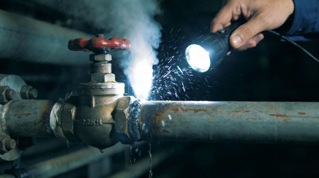
Valve internal leakage refers to the passage of fluid from the upstream side to the downstream side even when the valve is intended to be closed. Depending on the valve type and application, this leakage may occur across the disc and seat, ball and seat, gate and seat, or other internal sealing components. A small amount of leakage may initially appear insignificant, but continuous leakage can cause product loss, pressure instability, inaccurate process control, increased energy consumption, contamination, and accelerated equipment wear.
More importantly, internal leakage should not automatically be treated as a simple valve quality problem. In actual industrial applications, leakage can result from the interaction of valve selection, fluid properties, differential pressure, installation quality, operating procedures, actuator performance, piping stress, and maintenance practices. Therefore, an effective solution requires a full lifecycle approach rather than simply replacing the valve after every failure.
Before troubleshooting, maintenance personnel should distinguish internal leakage from external leakage. Internal leakage occurs through the valve's closed flow passage, allowing fluid to move from the inlet side to the outlet side. External leakage occurs when fluid escapes to the surrounding environment through areas such as the stem packing, bonnet gasket, body joint, drain connection, or other pressure-containing boundaries.
The consequences are also different. External leakage can create direct personnel, environmental, and equipment hazards because the fluid enters the surrounding environment. Internal leakage may remain invisible because the fluid stays inside the pipeline, but it can still seriously affect process performance. For example, a leaking isolation valve can allow a supposedly depressurized equipment section to remain pressurized, creating a potentially dangerous condition during maintenance.
The first troubleshooting step should therefore establish where the leakage is occurring, under what pressure conditions it occurs, and whether the valve is actually achieving its intended closed position.
A valve achieves shutoff by bringing two sealing surfaces into sufficient contact to prevent unacceptable fluid passage. Depending on the design, the sealing interface may use metal-to-metal contact, an elastomeric seat, PTFE or another fluoropolymer, or a combination of resilient and metallic components.
The required sealing performance depends heavily on differential pressure. When the upstream pressure is significantly higher than the downstream pressure, the pressure differential can force fluid through even a very small discontinuity between the sealing surfaces. This is why a valve that appears acceptable during one operating condition may exhibit leakage under another pressure condition.
The sealing mechanism also varies considerably by valve design:
| Valve Type | Typical Shutoff Mechanism | Common Internal Leakage Risks |
|---|---|---|
| Gate valve | Gate-to-seat contact | Seat damage, debris, incomplete closure |
| Globe valve | Disc-to-seat contact | Seat erosion, disc damage, incorrect closure |
| Ball valve | Ball-to-seat contact | Seat wear, particles, chemical degradation |
| Butterfly valve | Disc-to-seat contact | Seat wear, disc damage, misalignment |
| Check valve | Disc/plug-to-seat contact | Debris, spring failure, seat damage |
| Plug valve | Plug-to-body sealing | Wear, corrosion, improper lubrication |
| Control valve | Plug/seat or other throttling element | Erosion, cavitation, trim wear |
Understanding the specific sealing mechanism is essential because the same symptom can have completely different causes in different valve designs.
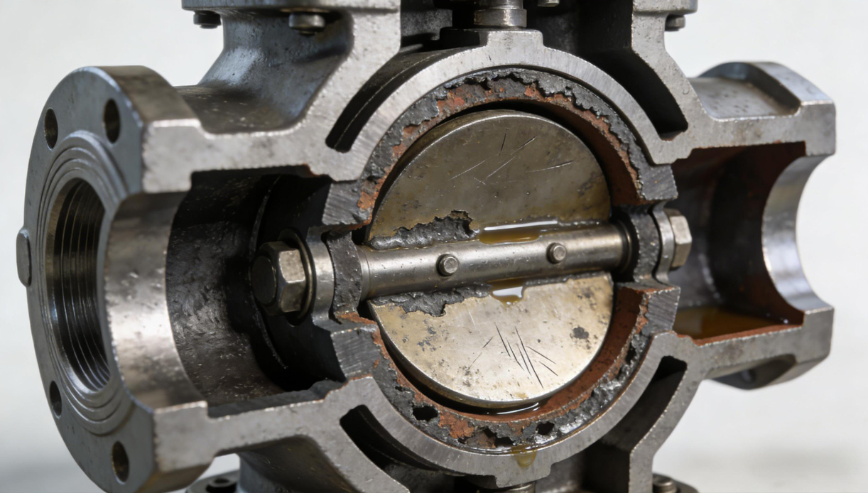
Damage to the valve seat or closing element is one of the most common causes of internal leakage. During operation, sealing surfaces can suffer from erosion, corrosion, cavitation, mechanical scratches, impact damage, or repeated wear. Once the sealing surfaces are no longer sufficiently smooth or correctly aligned, continuous contact may no longer be possible.
Erosion is particularly common in applications with high flow velocity or suspended particles. When fluid repeatedly passes through a narrow gap, the resulting local velocity can gradually remove material from the sealing surface. Corrosive fluids can produce another failure mechanism by chemically attacking the seat or disc.
Minor surface damage may sometimes be corrected through lapping or machining, depending on the valve design and manufacturer's repair requirements. If the seat or sealing element has experienced significant material loss, deformation, cracking, or corrosion, replacement of the affected component is generally more appropriate.
Maintenance personnel can monitor downstream pressure, flow, temperature, and other process indicators after the valve is closed. An unexpected downstream pressure increase may indicate internal leakage.
For critical equipment, valve disassembly and visual inspection can provide more direct evidence. Inspection should examine scratches, pitting, erosion patterns, corrosion products, deformation, and abnormal contact marks across the sealing surfaces.
A valve may remain mechanically functional while still leaking because foreign material has become trapped between the sealing surfaces. This is especially common in irrigation systems, water pipelines, wastewater applications, and industrial processes where suspended solids or crystallized materials may enter the flow path.
Sand, rust particles, welding slag, scale, process crystals, and other contaminants can prevent the disc, gate, ball, or plug from reaching its correct seating position. Even a small particle can create a microscopic leakage path.
A practical response depends on the valve type and manufacturer's operating instructions. In some applications, temporarily opening the valve slightly can increase flow velocity and help remove loose debris before the valve is slowly returned to the closed position. However, this method should not be used indiscriminately, especially where opening the valve could create a safety or process hazard.
Effective prevention usually combines several measures:
- Install suitable upstream strainers or filters where appropriate.
- Flush new piping before commissioning.
- Remove welding slag and construction debris during installation.
- Establish regular pipeline flushing procedures.
- Monitor suspended solids and process contamination.
- Inspect valves operating in high-particle environments more frequently.
The goal is not merely to clean the valve after leakage occurs but to prevent contaminants from reaching the sealing interface in the first place.
Not every apparent internal leak is caused by damaged components. In some cases, the valve simply has not reached its fully closed position.
This problem is particularly relevant to manually operated valves, valves installed in poorly accessible locations, and designs where the actual position cannot be easily observed. An operator may believe that a valve is closed because the handwheel has stopped moving, while the valve disc or gate has not actually reached the required seating position.
Over-tightening should also be avoided. Excessive force can damage the stem, actuator, seat, or other internal components.
Operators should follow the valve manufacturer's specified operating procedure and avoid using excessive force to compensate for resistance. Where possible, valve position indicators should be checked and maintained.
For automated valves, the actuator's travel limits, torque settings, feedback signals, and calibration should be verified. A valve may appear to be receiving a "close" command while its actuator is stopping before the actual mechanical end position.
The valve stem and transmission mechanism transfer operating force from the handwheel, gearbox, actuator, or other operating device to the closing element. If this force cannot be transmitted correctly, the valve may fail to achieve adequate shutoff.
Potential problems include bent stems, damaged threads, worn gears, loose couplings, actuator malfunction, incorrect travel limits, and excessive mechanical resistance.
In automated systems, the actuator should not be considered separately from the valve. Valve torque or thrust requirements must be compatible with the actuator output throughout the complete operating range. Incorrect sizing may result in insufficient closing force or excessive mechanical loading.
A structured inspection should include:
- Stem movement and alignment.
- Handwheel or gearbox condition.
- Actuator travel and torque settings.
- Mechanical coupling between actuator and valve.
- Open and closed position feedback.
- Unusual operating torque or thrust.
- Signs of stem corrosion or thread damage.
If the transmission system is defective, replacing the entire valve may not be necessary. Correctly repairing or recalibrating the operating mechanism can sometimes restore shutoff performance.
Soft-seated valves commonly use materials such as EPDM, NBR, FKM, PTFE, or other elastomers and fluoropolymers. These materials provide excellent sealing performance under suitable operating conditions, but they are not universally compatible with every temperature, pressure, and chemical environment.
Long-term exposure to elevated temperatures can accelerate aging. Certain chemicals can cause swelling, hardening, cracking, extraction, or other forms of material degradation. Repeated pressure cycling can also contribute to mechanical fatigue.
Material compatibility must therefore be considered during valve selection rather than after failure occurs.
The selection of a sealing material should consider:
| Parameter | Key Consideration |
|---|---|
| Temperature | Continuous and peak operating temperature |
| Pressure | Normal and maximum differential pressure |
| Medium | Chemical compatibility and concentration |
| Solids | Particle content and abrasiveness |
| Cycling | Frequency of opening and closing |
| Environment | UV, humidity, ozone, external temperature |
| Service life | Expected replacement interval |
A replacement seal should match the original design specification or an approved equivalent. Substituting a visually similar sealing material without checking compatibility can result in premature failure.
A valve that is technically functional may still be unsuitable for the actual application. Incorrect selection is therefore one of the most fundamental causes of recurring internal leakage.
The selection process should consider the fluid, pressure, temperature, flow rate, pipe size, pressure class, corrosion characteristics, solids content, required shutoff performance, and operating frequency.
For example, a soft-seated valve may provide excellent shutoff in clean water service but may not be suitable for a process containing abrasive particles. A valve with an inappropriate pressure rating may also be subjected to conditions beyond its design limits.
Engineers should evaluate at least the following factors before specifying a valve:
- Nominal size and connection standard.
- Pressure rating or pressure class.
- Maximum and minimum operating temperature.
- Fluid composition and chemical concentration.
- Required shutoff performance.
- Flow velocity and pressure drop.
- Suspended solids or crystallization tendency.
- Corrosion and erosion risk.
- Manual or automated operation.
- Required operating frequency.
- Applicable industry and project standards.
Correct selection is one of the most cost-effective ways to reduce leakage because it addresses the failure mechanism before the valve enters service.
Even a high-quality valve can experience leakage if it is incorrectly installed. Installation errors can introduce mechanical stress and misalignment into the valve body, making it difficult for internal components to maintain proper alignment.
Common problems include misaligned flanges, uneven bolt tightening, excessive pipe loads, incorrect flow direction, improper gasket installation, and inadequate support of the connected piping.
When flange bolts are tightened unevenly, the flange may deform or apply uneven loading to the valve connection. Excessive external pipe stress can similarly distort the valve body and influence the relationship between the sealing components.
Before installation, the piping system should be checked for cleanliness, alignment, support, and dimensional compatibility. The valve should not be used as a tool for forcing misaligned pipes into position.
During flange connection, bolts should be tightened progressively and according to the applicable installation procedure. Where a specific torque sequence or torque value is required by the manufacturer or project specification, it should be followed.
Valve orientation is also important. Some valve designs have specific installation requirements related to flow direction, actuator orientation, drainage, or maintenance access.
Fluids containing dissolved salts, minerals, suspended chemicals, or reactive compounds may form deposits inside valves. Scaling and crystallization can accumulate around seats, discs, stems, and other internal components.
Once deposits become sufficiently thick, they can physically prevent the valve from reaching the fully closed position. Hard crystals can also scratch sealing surfaces during subsequent operation.
This issue is particularly relevant in chemical processing, water treatment, desalination-related systems, brine service, and other applications involving concentrated solutions.
Preventive measures can include controlled flushing, appropriate process temperature management, regular inspection, and scheduled cleaning. In severe services, the valve design and materials should be selected with deposit formation in mind.
Maintenance teams should also investigate why scaling occurs rather than simply removing deposits repeatedly. If process conditions consistently create crystallization, repeated cleaning without addressing the underlying process may only provide temporary relief.
The valve body forms part of the pressure boundary and provides the structural framework that keeps internal components correctly positioned. Excessive mechanical stress, thermal cycling, abnormal pressure, corrosion, manufacturing defects, or external impact can result in deformation or cracking.
Body deformation can change the alignment between the seat and closing element. Even if the sealing components themselves remain undamaged, their relative geometry may no longer be correct.
Cracks are more serious because they may compromise pressure containment as well as internal sealing performance. In pressure-containing equipment, suspected cracking should be treated as a significant integrity issue rather than a routine adjustment problem.
Visual inspection, pressure testing, dimensional checks, and appropriate nondestructive examination may be required depending on the valve's service criticality.
Minor deformation may sometimes be repairable under an approved procedure, but pressure-boundary cracks generally require replacement or qualified repair according to applicable standards and manufacturer requirements. Improvised welding or field modification of pressure-containing valve bodies should be avoided.
A valve does not operate in isolation from the dynamic behavior of the pipeline. Rapid pressure changes, water hammer, thermal expansion, thermal contraction, and abnormal operating conditions can impose loads that exceed what the valve and its sealing system were designed to withstand.
Water hammer is particularly important in water supply, irrigation, and long pipeline systems. Rapid valve closure can generate pressure waves that travel through the pipeline and produce transient pressure spikes. Repeated hydraulic shocks can damage valve components and accelerate seat wear.
Temperature changes create another challenge. High-temperature service can accelerate seal degradation and cause thermal expansion, while low temperatures can affect material properties and create dimensional changes.
System-level measures may include:
- Controlling valve closing speed.
- Installing surge-control equipment where necessary.
- Using pressure relief or pressure-regulating devices.
- Avoiding sudden pump starts and stops.
- Monitoring transient pressure conditions.
- Selecting valve materials and seals for the full temperature range.
- Maintaining operating pressure within the valve's specified limits.
Leakage prevention therefore requires consideration of both steady-state and transient operating conditions.
When a valve is suspected of leaking internally, immediately replacing it is not always the most efficient approach. A structured diagnostic procedure can identify the actual failure mechanism and prevent repeated failures.
First determine whether the observed pressure or flow behavior is actually caused by the valve. Check downstream pressure, flow indicators, pressure gauges, temperature, and other relevant process signals.
Verify that the valve has physically reached the closed position. For automated valves, compare the control signal, position feedback, actuator travel, and actual mechanical position.
Record upstream and downstream pressures. A large pressure differential can significantly influence leakage behavior and may also affect the safety of inspection or maintenance activities.
Check the handwheel, gearbox, stem, actuator, coupling, travel limit, and torque or thrust settings. Mechanical transmission problems can mimic sealing failures.
If the service contains solids, crystals, rust, or other contaminants, investigate the possibility of foreign material trapped around the sealing surfaces.
If external troubleshooting does not identify the cause, isolate and depressurize the relevant section according to the site's safety procedure before disassembly. Inspect the seat, disc, gate, ball, plug, stem, guides, and other relevant components.
The objective should not simply be to identify the damaged component. Maintenance teams should ask why the component failed. Was the material unsuitable? Was the valve incorrectly installed? Was the fluid too abrasive? Was the valve repeatedly subjected to water hammer?
Root-cause analysis is what separates temporary repair from long-term reliability improvement.
Leakage testing should be performed according to the valve's applicable standard, project specification, and intended service. Different valve categories and applications may have different permissible leakage requirements.
For industrial valves, standards such as API 598 and relevant ISO or project-specific requirements may be used to establish inspection and pressure-testing procedures. For control valves, IEC 60534-4 provides requirements for production testing related to seat leakage.
The important point is that a valve's acceptable leakage level depends on its design, service, testing standard, and application. A valve should not be judged solely by whether absolutely zero leakage is observed unless the applicable specification explicitly requires that performance.
Testing should also reproduce relevant pressure and temperature conditions as closely as practical. A valve that passes a low-pressure shop test does not necessarily have identical behavior under every field operating condition.
Repeated internal leakage often indicates that maintenance is being performed reactively rather than preventively. A more effective strategy is to establish inspection intervals based on valve criticality and operating conditions.
Critical isolation valves protecting pumps, pressure vessels, chemical equipment, emergency systems, or major process lines may require more frequent inspection than low-consequence service valves.
A preventive maintenance program can include:
- Periodic functional opening and closing.
- Inspection of actuator and transmission components.
- Monitoring upstream and downstream pressure.
- Checking for abnormal temperature or flow behavior.
- Inspecting accessible external components.
- Cleaning strainers and filters.
- Reviewing leakage history.
- Replacing aging seals according to service conditions.
- Testing critical isolation valves.
- Recording all maintenance findings digitally.
Historical data is particularly valuable. If the same valve repeatedly develops leakage after a similar operating period, the maintenance team can investigate whether the underlying problem is material selection, process conditions, installation stress, or operating practice.
Different valve designs offer different advantages in terms of shutoff, throttling, pressure loss, solids handling, and maintenance.
Gate valves are commonly used for isolation because they can provide a relatively unobstructed flow path when fully open. They are generally not intended to serve as precision throttling devices because prolonged throttling can increase erosion and damage.
Ball valves are widely used where reliable quarter-turn isolation and tight shutoff are required. However, seat material selection becomes particularly important when the medium contains abrasive particles or when operating temperatures are high.
Butterfly valves are compact and economical for many large-diameter piping systems. Their performance depends strongly on seat material, disc condition, shaft alignment, and operating conditions.
Globe valves are commonly selected for throttling and flow regulation because their geometry allows better control characteristics. However, continuous throttling can expose the trim to erosion and cavitation, depending on pressure drop and fluid conditions.
Check valves have a different purpose: they prevent reverse flow rather than provide manual isolation. Their internal leakage can result from damaged seats, foreign particles, worn discs, spring failure, or unsuitable installation conditions.
One of the most important choices in valve selection is the sealing configuration. Soft-seated valves typically use elastomers or polymers to achieve very low leakage under suitable conditions. They are widely used in water, clean fluids, and many general industrial services.
Metal-seated valves use metallic sealing surfaces and are often selected for higher temperatures, severe service, abrasive media, or applications where polymeric seat materials may not be suitable.
Neither design should be regarded as universally superior. The correct choice depends on the actual combination of pressure, temperature, medium, particles, chemical compatibility, and required shutoff performance.
The purchase price of a valve represents only a small part of its potential lifecycle cost. A low-cost valve that repeatedly leaks may create significantly higher expenses through production losses, maintenance labor, replacement parts, emergency shutdowns, and secondary equipment damage.
A more appropriate evaluation considers:
| Cost Factor | Potential Impact |
|---|---|
| Initial purchase | Valve and accessories |
| Installation | Labor, gaskets, bolts, alignment |
| Maintenance | Inspection, repair, replacement |
| Leakage | Product and energy loss |
| Downtime | Production interruption |
| Safety | Incident and compliance risks |
| Service life | Replacement frequency |
| Reliability | Availability of the process |
For critical industrial systems, selecting a valve based solely on purchase price can therefore be misleading. Lifecycle reliability should be considered alongside initial cost.
The most effective way to reduce internal leakage is to manage the valve from specification through retirement.
Engineers should establish the process conditions first and then select the valve type, materials, sealing system, pressure rating, and actuator based on those conditions.
Installation teams should control alignment, piping stress, flange connection, cleanliness, flow direction, and operating mechanism setup. New pipelines should be properly flushed before valves are placed into normal service.
Operators should follow defined opening and closing procedures, avoid excessive force, and pay attention to abnormal pressure, vibration, noise, temperature, or flow conditions.
Maintenance teams should monitor critical valves according to their risk and operating environment rather than applying identical inspection intervals to every valve.
Maintenance records should include valve identification, service medium, installation date, inspection results, leakage history, repair records, seal replacement history, and test results. Such data helps engineers identify recurring failure patterns and improve future specifications.
When a closed valve is suspected of internal leakage, engineers and maintenance personnel can use the following checklist:
- Is the valve actually required to provide complete isolation?
- What are the upstream and downstream pressures?
- Has the temperature changed significantly?
- Is the medium clean, corrosive, abrasive, or prone to crystallization?
- Are there abnormal transient pressure events?
- Is the valve fully closed?
- Is the stem straight and operating smoothly?
- Is the gearbox or actuator functioning correctly?
- Are the travel limits correctly adjusted?
- Is there abnormal operating torque?
- Is the seat damaged?
- Is the disc, ball, gate, or plug damaged?
- Is the sealing material compatible with the medium?
- Are deposits or foreign particles present?
- Has the seal reached the end of its service life?
- Are the flanges aligned?
- Were bolts tightened correctly?
- Is excessive piping stress acting on the valve?
- Is the valve installed in the correct orientation?
- Was the pipeline adequately cleaned before commissioning?
Valve internal leakage is rarely caused by one isolated factor. Sealing surface damage, foreign particles, incomplete closure, stem or actuator problems, seal aging, incorrect valve selection, installation errors, crystallization, body deformation, and abnormal pressure or temperature conditions can all contribute to leakage.
For this reason, simply replacing a leaking valve may solve the immediate symptom without eliminating the underlying cause. A more effective approach is to establish a complete management process covering selection, design, installation, commissioning, operation, inspection, testing, maintenance, and root-cause analysis.
The key principle is straightforward: identify the leakage mechanism first, determine the root cause second, and select the corrective action based on the actual operating conditions. When engineers choose the correct valve type and sealing material, installation teams control alignment and piping stress, operators follow appropriate procedures, and maintenance personnel use condition-based inspection, internal leakage can be significantly reduced.
Reliable valve shutoff is ultimately not just a matter of choosing a better valve. It is the result of matching the valve to the service, controlling the installation environment, understanding the behavior of the fluid system, and maintaining the equipment throughout its complete lifecycle. This systematic approach helps extend valve service life, reduce energy and maintenance costs, improve process reliability, and keep industrial and municipal piping systems operating safely and efficiently.
Previous: Fluoropolymer-Lined Valves for Corrosive Media

Founded in 2013, Bosseal is a professional industrial valve manufacturer based in Suzhou, China. We specialize in the design and production of Ball Valves, Gate Valves, Globe Valves, Check Valves, Butterfly Valves, Plug Valves, and Piping Strainers. All our products are manufactured in strict compliance with international standards, including API, ASME, ISO, DIN, BS, and EN. With a strong focus on quality control and engineering capability, we are committed to providing reliable and high-performance valve solutions for global industrial applications.