Fire Valve Inspection and Maintenance Guide
Fire water supply valves must be inspected, tested, and maintained systematically to ensure that water can reach hydrants, sprinklers, and other firefighting equipment when needed. The most effective approach combines risk-based inspection schedules, functional testing, preventive maintenance, accurate documentation, and prompt corrective action in accordance with applicable fire safety codes. By verifying valve position, sealing performance, pressure conditions, alarm signals, and system response, facility managers can reduce the risk of hidden failures and maintain reliable fire protection.
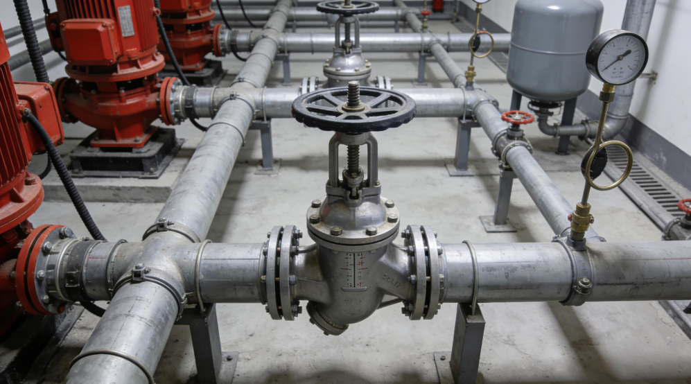
Fire water supply valves are essential components of building fire protection systems. They control the direction, distribution, and isolation of water throughout fire hydrant networks, automatic sprinkler systems, fire pump assemblies, and other water-based suppression installations. Although valves may appear to be relatively simple mechanical devices, their operating condition directly affects whether the overall system can deliver the required water flow and pressure during an emergency.
A fire protection system may include adequately sized pumps, correctly installed piping, and properly positioned sprinklers, yet still fail to perform as intended if a critical isolation valve is closed, a check valve is leaking internally, or an alarm valve cannot operate correctly. These failures can remain unnoticed during normal building operation because the system may not be required to deliver emergency-level water flow for months or years.
Valve maintenance should therefore be treated as an essential part of fire safety management rather than an occasional mechanical inspection. The National Fire Protection Association's NFPA 25 standard establishes inspection, testing, and maintenance requirements for water-based fire protection systems, including provisions for valves, system impairments, and corrective actions. Its underlying objective is to maintain a reasonable degree of protection for life and property through systematic verification of system condition.
Several types of valve failure can compromise fire water supply reliability:
- Incorrect valve position: A normally open control valve may be closed accidentally during maintenance, construction, or routine building operations.
- External leakage: Damaged packing, worn seals, loose connections, or corrosion may cause water leakage and gradual deterioration of equipment.
- Internal leakage: A valve that should prevent reverse flow or provide isolation may allow water to pass through its sealing surfaces.
- Mechanical seizure: Corrosion, sediment accumulation, damaged threads, or inadequate lubrication may prevent a valve from opening or closing as required.
- Signal transmission failure: A supervisory switch may fail to report a control valve's position change to the fire alarm or building management system.
- Pressure and flow abnormalities: Partially closed valves, obstructions, or faulty components may restrict the available water supply.
The significance of each defect depends on the valve's location, function, redundancy, and effect on the protected area. A minor external leak does not necessarily create the same immediate hazard as a closed main control valve. Inspection findings must therefore be evaluated according to their potential impact on firefighting capability.
Fire valve inspection programs should be developed using the applicable national regulations, approved system design documents, manufacturer instructions, and relevant technical standards. In China, GB 50974-2014, the Code for Design of Fire Water Supply and Hydrant Systems, is an important reference for fire water supply and hydrant system design and associated technical requirements. However, design provisions should not automatically be interpreted as establishing every routine maintenance interval.
For international projects, NFPA 25 provides a widely recognized framework for inspecting, testing, and maintaining water-based fire protection systems. The applicable edition, local adoption status, authority having jurisdiction, and project-specific requirements must be confirmed before establishing a compliance schedule.
These three activities serve different purposes and should be documented separately.
| Activity | Primary purpose | Typical examples |
|---|---|---|
| Inspection | Identify visible defects and abnormal conditions | Checking valve position, leakage, corrosion, identification signs, and supervisory devices |
| Testing | Verify actual functional performance | Operating a valve, checking alarm activation, or evaluating reverse-flow prevention |
| Maintenance | Restore or preserve the required operating condition | Cleaning, adjusting, lubricating where permitted, repairing, and replacing components |
A visual inspection cannot establish that a valve operates correctly under all conditions. Similarly, a successful functional test does not eliminate the need to inspect for corrosion, damaged components, or deterioration that may develop over time.
A comprehensive maintenance program integrates all three activities according to the component's function and the applicable requirements.
Daily, monthly, and quarterly checks can form part of a facility's internal management program, as described in many operational procedures. However, these intervals should not be presented as universal statutory requirements for every fire valve. Actual frequencies depend on the applicable code, valve type, system configuration, manufacturer instructions, and risk assessment.
A practical management framework may include the following levels:
- Routine checks: Identify obvious leakage, incorrect valve positions, damaged identification signs, and environmental hazards.
- Monthly functional reviews: Assess selected operating conditions, accessibility, supervisory arrangements, and outstanding maintenance issues according to the approved plan.
- Quarterly system reviews: Review alarm transmission, valve monitoring, maintenance records, and relevant system-level test results.
- Annual or code-specified testing: Perform prescribed operational tests, inspections, and performance verification at the frequencies required by the governing standard.
- Condition-triggered inspections: Conduct additional checks following repairs, unusual pressure events, accidental valve operation, severe weather, or reports of abnormal system behavior.
This framework should be reconciled with mandatory requirements before implementation. For example, NFPA 25 includes specific inspection and testing provisions for control valves and check valves, rather than applying one identical schedule to every component.
Effective inspection begins before maintenance personnel touch the equipment. Preparation helps reduce operational disruption, improves measurement accuracy, and prevents maintenance activities from introducing new risks into the fire protection system.
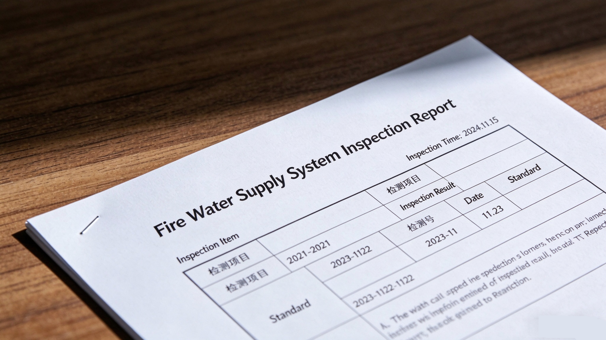
The exact equipment required depends on the valve and the inspection procedure. Commonly used items include:
- Calibrated pressure gauges suitable for the expected system pressure.
- Appropriate wrenches and manufacturer-approved operating tools.
- Flashlights, inspection mirrors, and basic cleaning equipment.
- Approved lubricants where permitted by the valve manufacturer.
- Replacement packing, gaskets, fasteners, or other compatible spare parts.
- Valve identification lists, inspection forms, and maintenance records.
- Personal protective equipment and barriers for controlling access to the work area.
- Suitable gas-monitoring and ventilation equipment where confined-space hazards may exist.
A pressure gauge with a range of 0–2.5 MPa may be suitable for certain installations, but it is not universally appropriate. The instrument range, accuracy, pressure rating, connection type, and calibration status should match the actual test conditions. Selecting a gauge solely because it is commonly used can result in inaccurate readings or unsafe operation.
Fire protection maintenance can introduce hazards if the system is isolated, depressurized, or operated without proper coordination. Before work begins, personnel should identify the valve's function, determine which protected areas could be affected, and establish an approved work plan.
Key precautions include:
- Review system drawings. Confirm the valve's location, upstream and downstream connections, normal position, and relationship to pumps, tanks, hydrants, sprinklers, and alarm devices.
- Assess impairment risks. Determine whether closing the valve will reduce protection to an occupied building or critical area.
- Notify responsible personnel. Coordinate with the facility manager, fire safety team, monitoring center, and other relevant parties.
- Control the work area. Prevent unauthorized operation and clearly identify equipment undergoing maintenance.
- Use safe operating procedures. Operate valves at a controlled rate in accordance with the manufacturer's instructions and the approved system procedure.
- Inspect valve chambers safely. Where a valve is installed in a pit or chamber, assess flooding, ventilation, access, and atmospheric hazards before entry.
Valve chambers should never be entered solely on the assumption that outdoor access guarantees a safe atmosphere. If confined-space hazards may exist, appropriate entry procedures, atmospheric testing, ventilation, and rescue arrangements are necessary.
Before isolating a fire protection component, the responsible team should determine the extent and duration of the impairment. Alternative protection, temporary fire watch arrangements, or restrictions on hazardous activities may be required under applicable procedures.
The maintenance team should record the isolation time, affected system, responsible person, expected completion time, and required notifications. Once work is finished, the system must be restored to its normal operating condition, and any required verification and notifications must be completed.
Routine inspections should prioritize conditions that can be identified without unnecessarily disrupting the fire protection system. A consistent checklist helps personnel detect deterioration early and prevents important details from being overlooked.
Every critical control valve should be checked against its documented normal position. Depending on the application, a valve may be required to remain fully open or fully closed. The correct position must be established from system drawings, approved operating procedures, and valve identification.
Inspectors should verify that:
- The valve is in its required operating position.
- The handwheel, gearbox, operating nut, or actuator is intact.
- The valve is accessible and can be operated using the appropriate tools.
- Position indicators are readable and consistent with the actual valve position.
- Locks, seals, or supervisory arrangements are intact where required.
- No stored materials, construction work, or unauthorized modifications obstruct access.
An open-looking handwheel position is not always sufficient evidence that a valve is fully open. Some valve types have different travel characteristics, and the position indicator may become inaccurate if the mechanism is damaged or incorrectly adjusted.
Inspectors should examine valve bodies, bonnets, stems, packing glands, flanges, threaded connections, and nearby pipe joints. Signs of leakage include water droplets, persistent dampness, mineral deposits, rust staining, and deterioration of protective coatings.
Corrosion is particularly important in outdoor installations, underground valve chambers, coastal environments, and areas exposed to chemicals or repeated moisture. Surface rust does not automatically mean that a valve must be replaced, but advanced corrosion, pitting, deformation, or material loss may compromise pressure integrity.
Where leakage is found, maintenance personnel should identify its source before tightening fasteners or adjusting packing. Excessive tightening can damage sealing components or increase operating torque. Any repair must follow the manufacturer's instructions and applicable pressure-system safety procedures.
Clear identification reduces the likelihood of accidental operation and speeds up emergency response. Each critical valve should be identifiable through suitable labels, location references, and system documentation.
Inspection personnel should confirm that valve tags match the corresponding drawings and maintenance records. If an asset has been relocated, replaced, or renumbered, the documentation should be updated promptly.
A useful inspection record includes the date, asset identification number, observed condition, test results where applicable, deficiencies, corrective actions, and the name of the responsible inspector.
Different valve types perform different functions within a fire water supply network. Their inspection procedures must reflect those differences rather than relying on a single generic checklist.
Control valves regulate or isolate water flow to particular sections of a fire protection system. Common designs include gate valves, butterfly valves, and other approved isolation valves.
The inspection should confirm the correct position, accessibility, absence of external leakage, and condition of any locking or supervisory equipment. Where required by the applicable standard, the valve should be operated through its prescribed range and returned to its normal position.
Operating resistance should be evaluated carefully. Excessive torque may indicate corrosion, damaged internal components, packing problems, debris, or a mechanical obstruction. Personnel should not force a seized valve with an extended lever or unauthorized tool because this may damage the stem, gearbox, or internal seating surfaces.
After a functional test, the valve must be returned to its required operating position and any supervisory or locking arrangements restored.
A signal valve, commonly associated with a supervisory switch, allows the fire protection system to monitor a control valve's position. Its purpose is not merely to open or close the water passage; it also helps indicate whether the system remains in its intended configuration.
The inspection should cover both mechanical and electrical performance:
- Confirm that the valve's physical position corresponds to its indicator.
- Inspect the supervisory switch, wiring, enclosure, and mounting.
- Verify that the control system receives the appropriate status signal.
- Confirm that a change in valve position produces the required supervisory indication within the specified operating conditions.
- Check that the signal clears correctly when the valve is restored, where applicable.
A valve may operate mechanically while its supervisory switch or wiring fails. Conversely, a control panel may display a normal status even if the sensing mechanism is incorrectly adjusted. Functional verification should therefore examine the relationship between the physical valve position and the received signal.
The applicable fire alarm and supervisory requirements should be consulted when defining the test procedure and acceptance criteria.
Alarm valve assemblies are used in applicable automatic sprinkler systems to detect water flow and initiate alarm functions. Depending on the system configuration, they may include alarm valves, trim piping, pressure switches, retard chambers, alarm lines, and associated accessories.
Inspection should examine the assembly for leakage, corrosion, damaged fittings, obstructed drain lines, and abnormal pressure conditions. The valve's normal operating state should be consistent with the approved system design.
A prescribed water-flow or alarm test should verify that water movement activates the expected alarm mechanism and that the associated signals reach the designated monitoring or fire alarm system. The test should also confirm that the system can be restored to its normal operating state.
The acceptance criteria should follow the manufacturer's instructions and applicable installation and maintenance standards. Alarm response time, pressure conditions, and discharge behavior should not be judged against arbitrary values that are unrelated to the system design.
Check valves permit flow in the intended direction and help prevent reverse flow. In fire water systems, they may be installed in pump discharge piping, interconnected water supply lines, or other locations where reverse flow could compromise system performance.
A check valve can develop internal leakage even when no external leak is visible. Worn sealing surfaces, damaged discs, foreign material, corrosion, or impaired spring mechanisms can prevent effective closure.
A suitable inspection and testing program should consider:
- External leakage and physical damage.
- Abnormal vibration, noise, or water hammer.
- Pressure behavior during pump startup and shutdown.
- Evidence of reverse flow or pressure loss.
- Internal inspection at the interval required by the applicable standard.
- Cleaning, repair, or replacement of damaged internal components.
Where reverse-flow performance cannot be established through external observation, appropriate testing or internal examination may be necessary. NFPA 25 includes dedicated provisions for check valve inspection and maintenance, illustrating why these components require procedures specific to their function.
Pressure-regulating components require additional attention because their performance affects the pressure available to downstream equipment.
A pressure-reducing valve must maintain the intended downstream pressure under the relevant operating conditions. A pressure-relief valve must operate according to its approved setting and application when the relevant pressure threshold is reached.
Maintenance personnel should verify pressure readings using suitable calibrated instruments and confirm that the test conditions match the manufacturer's procedure. Improper adjustment may lead to inadequate downstream pressure, excessive pressure, nuisance discharge, or damage to connected equipment.
These components should not be adjusted solely to eliminate an abnormal reading. The underlying cause may involve a pump control issue, an incorrect gauge, a blocked sensing line, or a change in the water supply.
Valve inspection must be connected to broader fire protection system performance. A valve that appears satisfactory in isolation may still contribute to inadequate water delivery if the surrounding system contains restrictions, pressure abnormalities, or control problems.
Pressure readings should be interpreted in relation to the system design, expected operating conditions, and relevant acceptance criteria. A single static pressure reading does not establish that the system can deliver the required flow during a fire.
Where prescribed, flow tests and pressure measurements should evaluate the system's response under appropriate operating conditions. The results should be compared with commissioning records, approved design information, and previous test data to identify meaningful changes.
For example, a declining pressure trend may indicate a developing restriction, pump deterioration, water supply changes, or instrument error. Further investigation is needed before attributing the change to a particular valve.
Fire pumps and their associated valves must function as an integrated system. Improper valve positioning can restrict pump suction, impede discharge, or interfere with the intended flow path.
Testing should follow the approved pump and system procedures. Personnel should check relevant valve positions, observe pressure and flow behavior, and investigate unusual vibration, noise, or pressure fluctuations.
Sudden valve operation can generate transient pressure changes, including water hammer. Controlled operation helps reduce mechanical stress, but the required procedure must be determined by the system configuration and manufacturer's guidance.
After testing, all affected valves should be returned to their prescribed positions, and any alarms, supervisory signals, or temporary arrangements should be checked and restored.
Restoration is a critical stage of every maintenance activity. Completing a repair does not automatically mean that the fire protection system is ready for service.
Before closing the work order, responsible personnel should verify that:
- All repaired components are correctly assembled.
- Required pressure or leakage checks have been completed.
- Control valves are in their documented normal positions.
- Supervisory devices and alarm functions are operational where applicable.
- Temporary isolations and restrictions have been removed.
- Relevant personnel and monitoring services have been notified that the system is back in service.
- Test results and outstanding defects have been recorded.
The final restoration check should be documented and independently reviewed where required by the facility's procedures.
A structured fault-response process helps prevent temporary repairs from concealing underlying problems. Maintenance personnel should identify the defect, assess its impact on fire protection, select an appropriate corrective action, and verify the result.
A valve that is difficult to operate may have corroded moving parts, damaged threads, excessive packing compression, accumulated debris, or a faulty gearbox.
The initial response should be to determine the valve type and inspect its external condition. Where permitted, personnel may clean accessible components or apply manufacturer-approved lubricant to designated points. Lubricant should never be introduced into an unsuitable part of the mechanism or into the waterway without explicit approval.
If the valve remains difficult to operate, it may require controlled disassembly, internal inspection, component replacement, or complete replacement. A valve should not be forced merely to satisfy a scheduled test.
External leakage may originate from stem packing, bonnet gaskets, flange joints, threaded connections, or damaged valve bodies. Internal leakage may result from worn seats, debris, or damaged closure elements.
The appropriate response depends on the source and severity of the leak. Some packing or gasket defects can be repaired using approved procedures, while severe corrosion, cracked bodies, or irreparable sealing damage may require valve replacement.
Repairs should use compatible materials and approved components. Following maintenance, the valve should undergo the required leakage or functional checks before the system is returned to service.
If the control panel indicates that a valve is closed when it is physically open, or fails to report a genuine position change, the cause may involve switch adjustment, damaged wiring, incorrect configuration, or a faulty monitoring input.
Troubleshooting should verify the mechanical position, switch operation, wiring continuity, and received signal. Electrical work must be performed by appropriately qualified personnel, and alarm monitoring arrangements should be managed during testing.
The system should not be considered fully restored until both the mechanical valve condition and required supervisory functions have been verified.
Reverse flow may arise from damaged sealing surfaces, trapped debris, a worn disc, or failure of an associated component. Depending on the system, the consequences may include pressure loss, unintended circulation, or interference with pump and water supply operation.
Personnel should investigate pressure trends, pump operating conditions, and the relevant flow path. If internal examination is necessary, the valve should be isolated using an approved procedure and inspected according to the manufacturer's instructions.
Replacing a faulty check valve without investigating recurring contamination or abnormal operating conditions may lead to repeated failures.
Reliable documentation is essential for demonstrating that fire protection equipment has been maintained and that identified defects have been addressed. An asset register also helps maintenance teams plan future inspections, track component history, and identify recurring problems.
Each critical valve should have a unique asset identifier linked to its physical location and system function. A useful register may include the following fields:
| Record field | Information to capture |
|---|---|
| Asset identification | Unique valve number and tag |
| Technical information | Valve type, size, pressure rating, manufacturer, and model |
| Installation details | Building, floor, room, riser, or valve chamber |
| System function | Isolation, reverse-flow prevention, alarm operation, or pressure regulation |
| Required position | Normally open, normally closed, or another specified operating state |
| Inspection history | Inspection dates, observations, and responsible personnel |
| Test results | Pressure readings, operational findings, and alarm verification |
| Defect management | Fault description, severity, corrective action, and completion date |
| Replacement history | Replaced components, parts used, and relevant documentation |
Digital maintenance systems can make these records easier to search and update. Barcode or QR-code identification can link the physical valve to its inspection history, drawings, maintenance instructions, and outstanding work orders.
However, digitization alone does not guarantee reliability. The information must remain accurate, accessible to authorized personnel, and consistent with the actual installed equipment.
Historical data can reveal recurring leakage, repeated actuator problems, corrosion patterns, or unexplained changes in pressure and test results. Maintenance managers can use this information to prioritize inspections and investigate root causes.
For example, repeated packing leakage at valves in the same outdoor area may indicate an environmental exposure issue or a common maintenance problem. Frequent supervisory signal failures may point to inadequate installation practices or recurring electrical faults.
Trend analysis should support engineering judgment rather than replace physical inspection. Abnormal data should trigger investigation, while the absence of recorded faults should not be treated as proof that a valve is functioning correctly.
Many facilities supplement routine maintenance with periodic reviews by qualified fire protection contractors or independent inspection organizations. These reviews can help identify gaps in maintenance procedures, verify documentation, and evaluate whether the system has been restored correctly following repairs.
Where an annual review or third-party inspection is required by law, the applicable approval conditions, fire safety regulations, and local authority requirements should be followed. In other cases, independent assessment may form part of a facility's risk management program.
An independent report can be particularly useful when a building has undergone major alterations, experienced recurring system faults, changed occupancy, or modified its water supply arrangements. However, a report does not automatically establish compliance if required tests were omitted or significant defects remain unresolved.
NFPA 25 distinguishes routine inspections from more involved testing and maintenance activities, with requirements varying by component and system type. Facilities should therefore develop their schedules from the applicable standard rather than assuming that one annual inspection can replace all required activities.
Environmental conditions can affect valve reliability, particularly in exposed installations and underground chambers. Seasonal maintenance should account for local climate, equipment location, and the design of the fire water supply system.
Freezing conditions can damage valve bodies, seals, pipework, and associated accessories. Ice formation may also obstruct operating mechanisms or prevent water from draining properly.
Winter preparations should include checking exposed piping, insulation, approved heat-tracing systems, enclosure integrity, and drainage arrangements where applicable. Underground chambers should be examined for standing water and damaged covers.
Dry-pipe and other specially designed systems require maintenance procedures appropriate to their configuration. Personnel should not assume that adding heat or applying insulation alone is sufficient to protect every type of installation.
After freezing weather, inspections should look for cracks, leakage, damaged coatings, and abnormal operating resistance. Suspected freeze damage should be evaluated before the affected equipment is relied upon for emergency service.
High temperatures, humidity, and prolonged moisture exposure can accelerate deterioration of protective coatings, electrical enclosures, seals, and metallic components.
During warm or wet seasons, maintenance personnel should examine valve chambers for flooding, verify drainage, and ensure that covers and protective enclosures remain intact. Ventilation should be provided where appropriate to the chamber design and safety requirements.
Coastal environments and industrial sites may require more frequent condition assessments because salt, chemicals, or airborne contaminants can accelerate corrosion. The inspection interval should reflect actual exposure conditions rather than relying exclusively on a standard calendar schedule.
Not all valves present the same level of risk. A valve controlling the principal supply to a large sprinkler installation may have a different consequence of failure from a valve serving a limited, separately protected section.
Risk-based maintenance combines the probability of failure with the consequences of losing the component's intended function. It can help facility managers prioritize resources without reducing mandatory inspection or testing requirements.
A useful assessment can consider:
- Criticality: How many protected areas depend on the valve?
- Failure history: Has the valve experienced repeated leakage, seizure, or signal faults?
- Environmental exposure: Is it exposed to flooding, freezing, chemicals, or severe corrosion?
- Redundancy: Is an approved alternative water supply or flow path available?
- Detectability: Would a fault be identified promptly by routine inspection or supervisory monitoring?
- Repair accessibility: Can the valve be inspected and repaired without major operational disruption?
High-risk components may justify additional condition monitoring, more detailed record reviews, or supplementary inspections, provided these measures are consistent with the approved system design and applicable requirements.
Preventive maintenance aims to identify deterioration before functional failure occurs. Corrective maintenance restores equipment after a defect has been discovered.
A mature program uses both approaches. Preventive activities include scheduled inspections, prescribed functional tests, environmental protection, and review of historical performance. Corrective activities include fault diagnosis, component repair, replacement, and post-maintenance verification.
The most important performance measure is not simply the number of inspections completed. It is whether the required tasks were performed correctly, deficiencies were resolved promptly, and the system was returned to a verified operational condition.
Fire water supply valve inspection and maintenance are fundamental to the reliability of building fire protection systems. Control valves, signal valves, alarm valve assemblies, check valves, and pressure-regulating components each perform distinct functions, so their inspection and testing procedures must reflect their design, operating conditions, and safety significance.
A reliable maintenance program combines routine visual checks, prescribed functional testing, safe work procedures, accurate asset records, seasonal protection, and timely corrective action. By following applicable requirements such as GB 50974-2014 and the relevant provisions of NFPA 25, while verifying the correct edition and local applicability of each standard, facility managers can improve system readiness and reduce the likelihood of preventable failures.
Ultimately, effective valve maintenance is not just about keeping individual components in good condition. It is about ensuring that the entire fire water supply system can perform its intended function when an emergency occurs, protecting occupants, property, and critical operations.
